← Xvisio SDK Documentation Home Page
Xvsdk Viewer
1 Overview
Xvisio Viewer is used for testing or evaluating Xvisio devices by user or developers.
2 Xvsdk Viewer User Guide
2.1 Main Interface
- Connect Xvisio deivce with USB cable.
- Start "xvsdk-viewer". The main interface will show once the device is connected successfully:
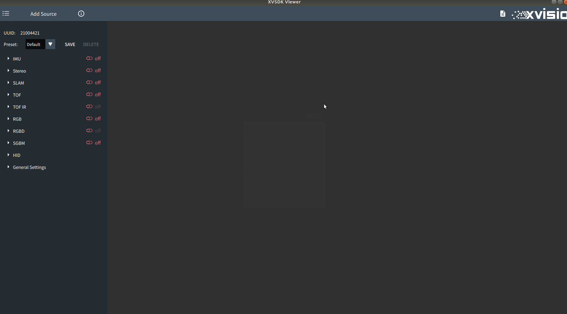
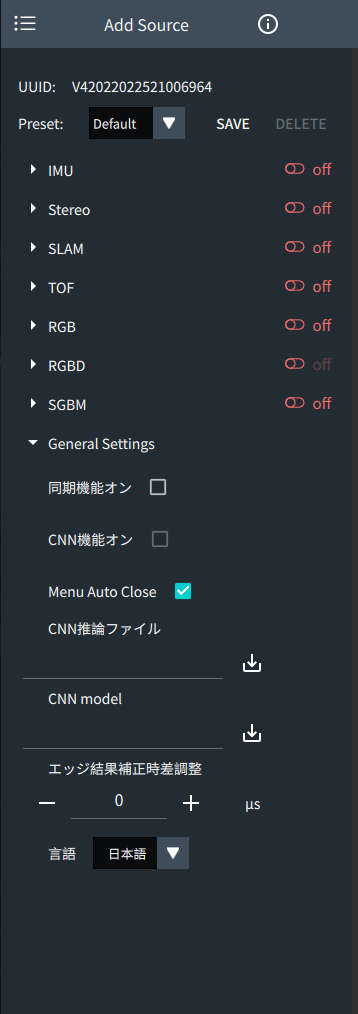
- Click button "Add Source", all the connected devices will be shown:

- Click "Info"
 ,all the detail information of devices and software will be shown:

It includes the version numbers of software, SDK, firmware and hardware, as well as the specific functions supported by the current device. - Click menu
 will open or close the current menu:

2.2 Function Introduction
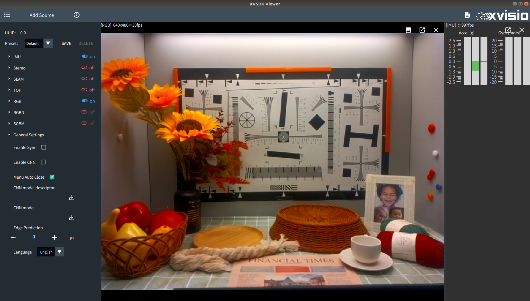
xvsdk-viewer allows user to select and configure IMU,Stereo,Slam,TOF,TOF IR,RGB,RGBD,SGBM and RGB. This section provides an overview of user-defined configurations. User can click an item in the menu to expand the supported configuration items. After completing the configuration, user must click the button  to start the current stream data.
2.2.1 IMU
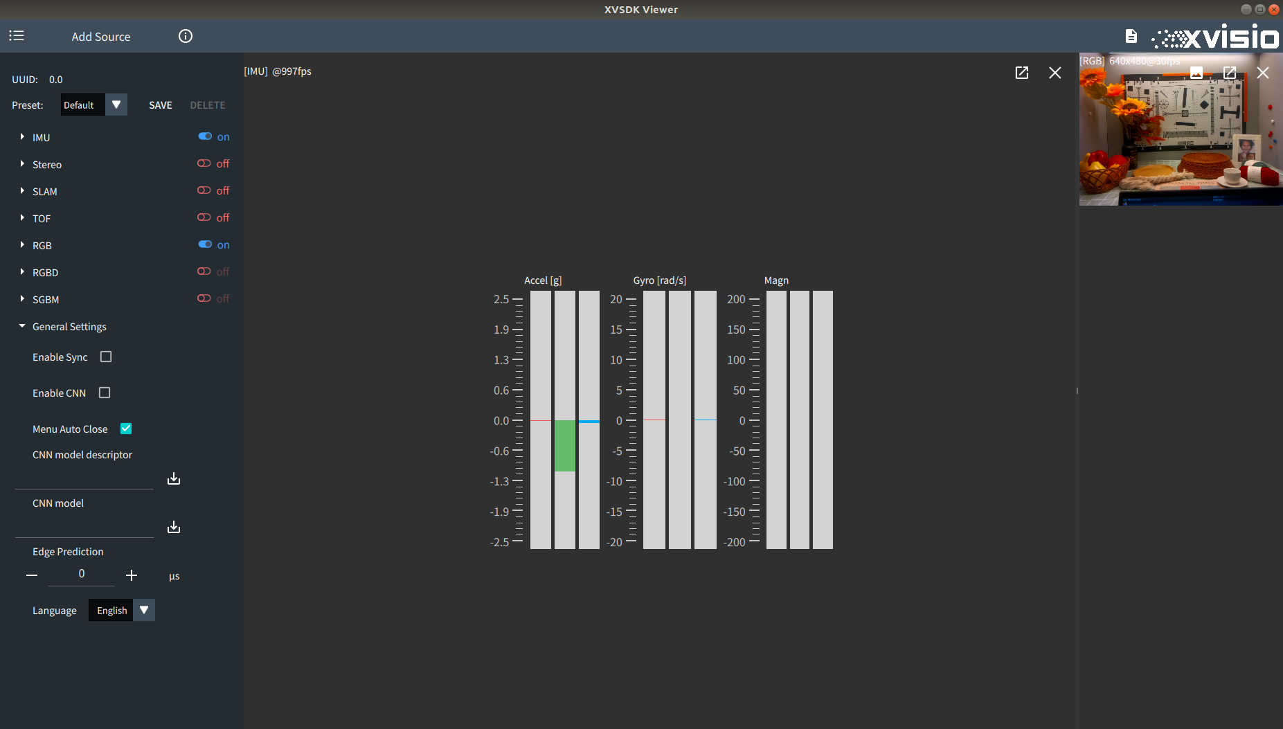
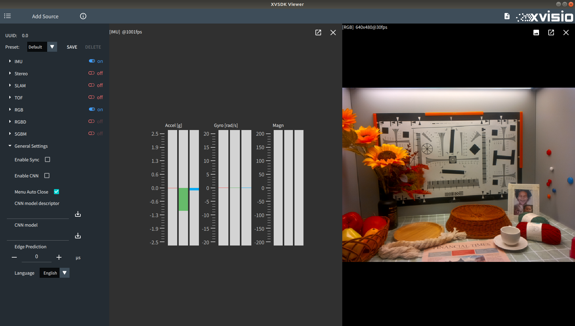
- Start "IMU" to get IMU data:

- Set IMU mode in menu:
- VSlam only
- VSlam+IMU
- IMU only
- Fusion on host
2.2.2 Stereo
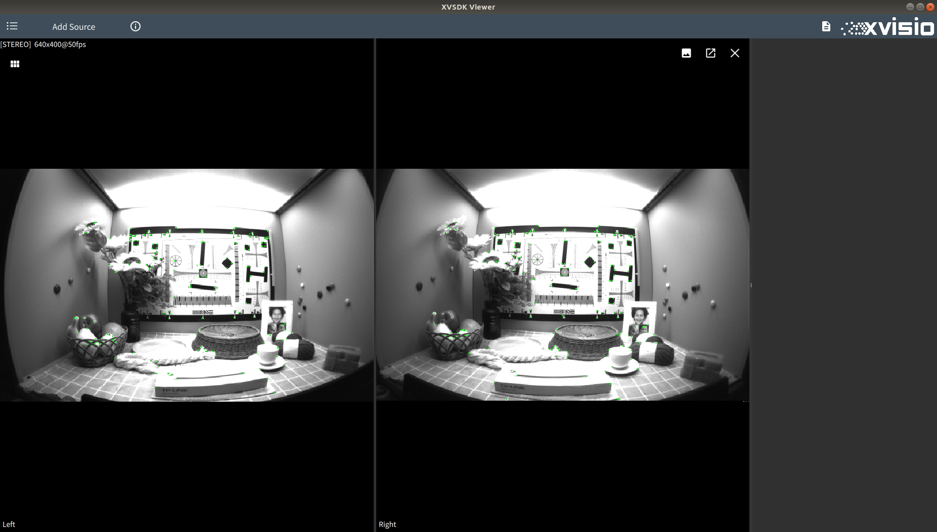
- Start Stereo to enable Fisheye camera:

- Set resolution to VGA or 720P (supported firmware) in menu:
- VGA is 640*480
- 720P is 1280*720
- Enable "Auto Exposure" to set auto exposure. If manual setting is required, you can cancel enabling the "Auto Exposure", and set the "Gain" to obtain brightness, and adjust the "Brightness" to set the maximum exposure time (note that this function will also adjust the image effect of sgbm).

- Click
 in "Stereo" to turn on/off the right camera of binocular fisheye camera.
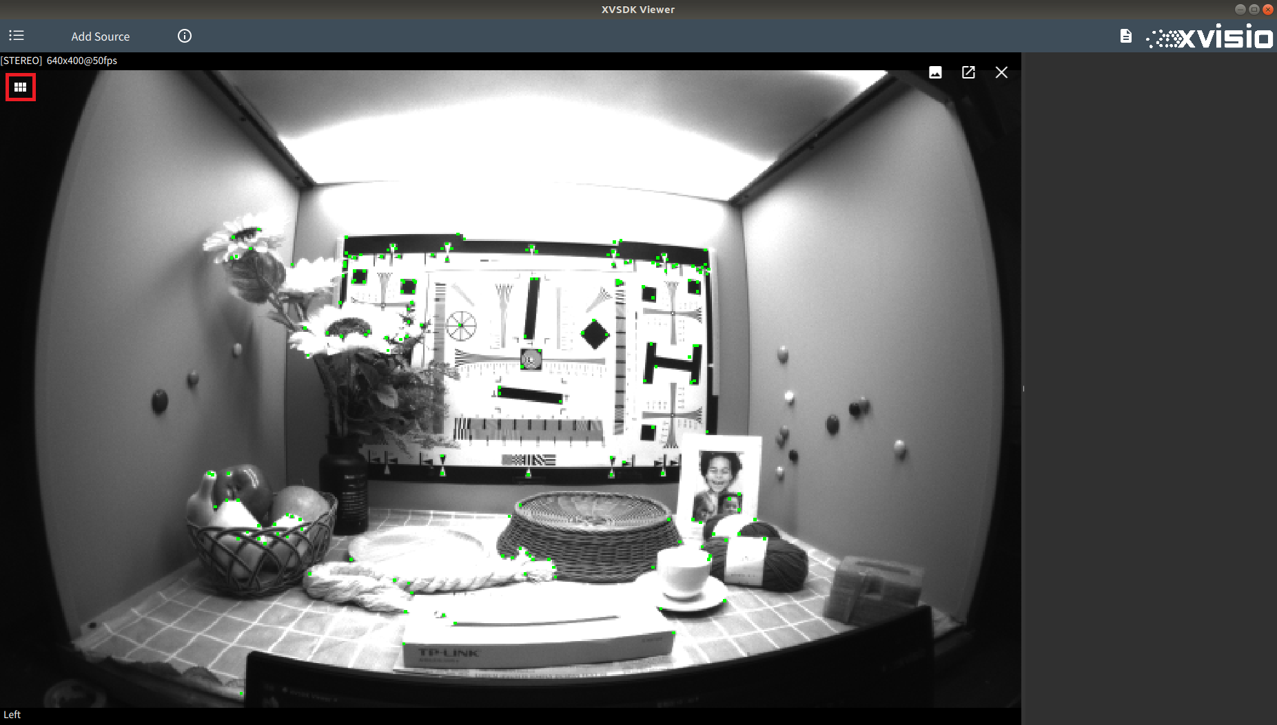
the image is shown as below:
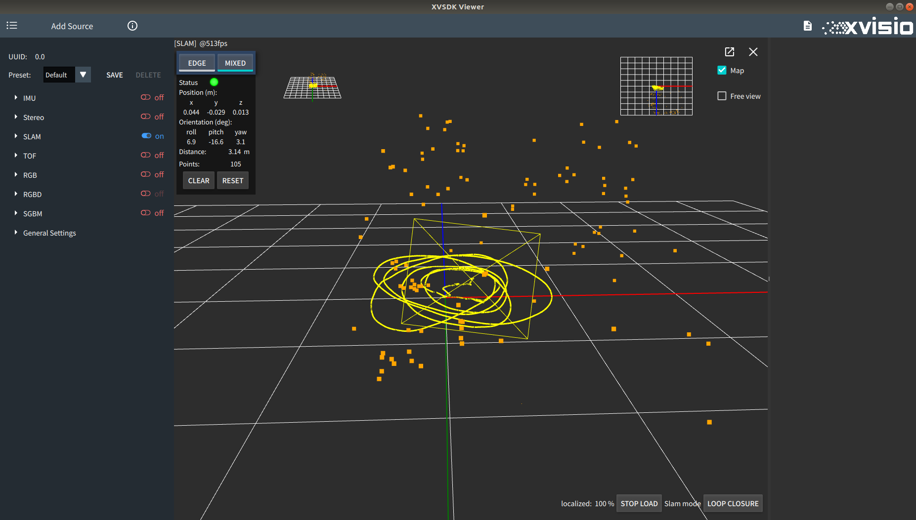
2.2.3 Slam
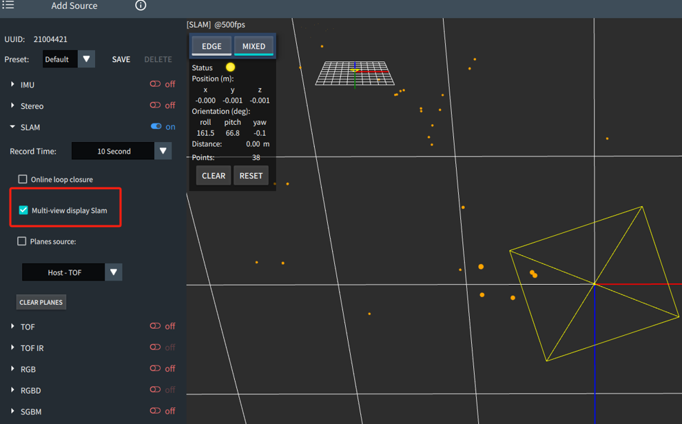
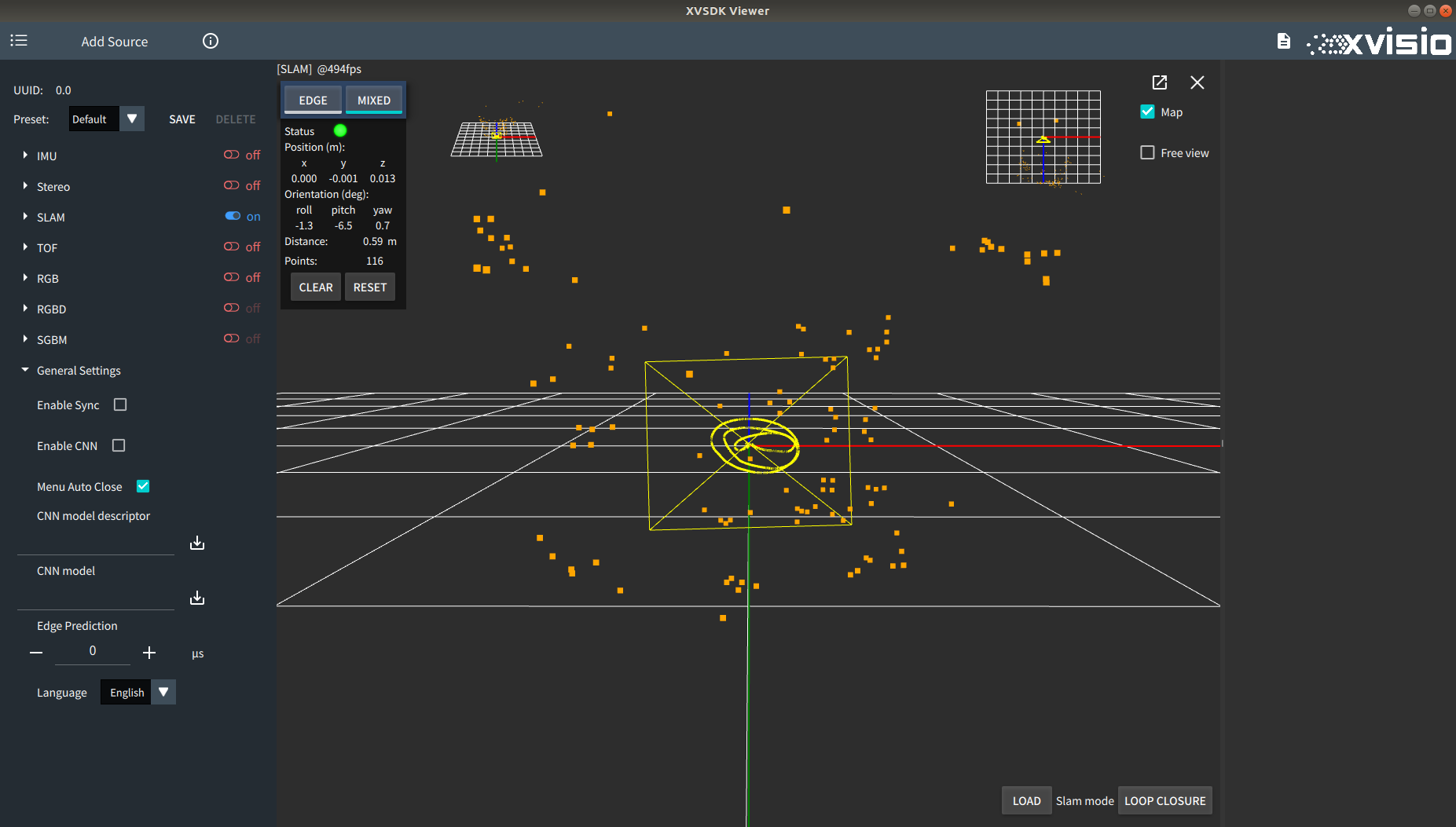
- Enable "Slam" to get Slam image:
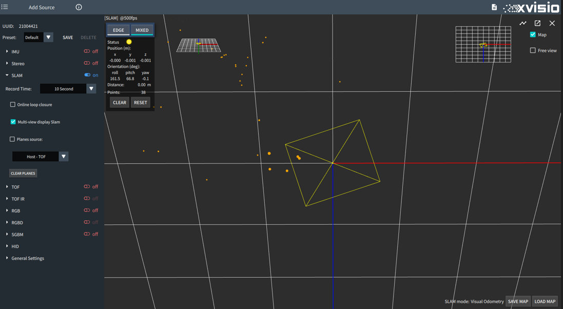
- The aerial view and plan view of slam will be displayed in the upper left and right corners of the interface. Switch enable or disable the dispaly by option "Multi-view display Slam" in menu. Only home view is displayed after diabling the display:
Click other display to switch to the main display:
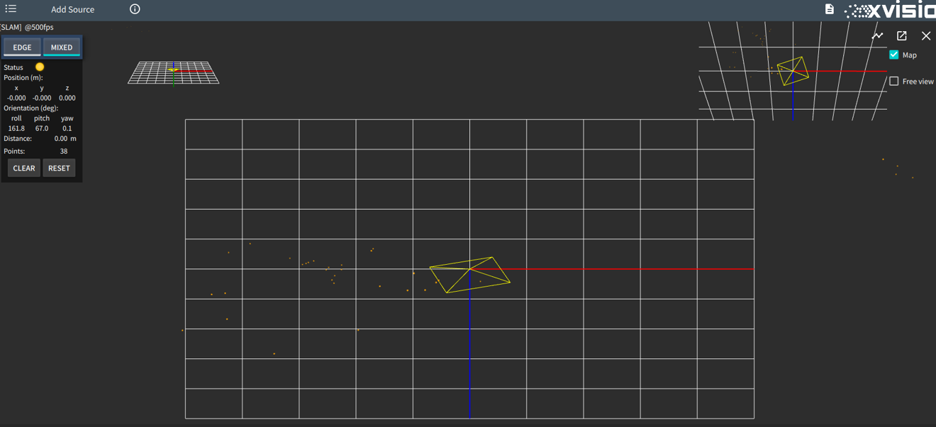
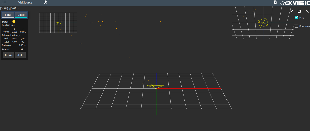
- You can control whether to obtain slam feature points by switching the "Map" option in the upper right corner:
You can control whether to turn on the free view by switching the option "Free view" in the upper right corner:

- In the control menu in the upper left corner, you can switch the Slam view of the corresponding mode by selecting "EDGE" or "MIXED":
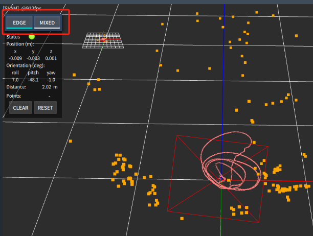
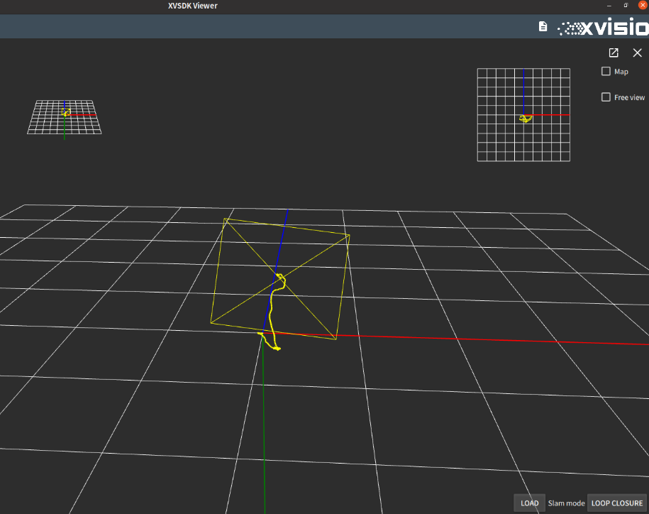
After moving the Slam trajectory, you can click "CLEAR" to clear the drawn track, or click "RESET" to clear the track and reset to the origin.

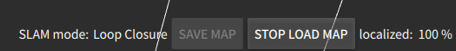
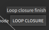
- In Mixed mode, click "LOOP CLOSURE" in the lower right corner of the screen to enable the CSlam mapping function.
After startup, the mobile device will save the trajectory information according to the moving path. Click "VISUAL ODOMETRY" to stop the function.
Then click "Load" on the left to load the saved trajectory information, and the matching degree prompt will be displayed at the bottom:
Click "STOP LOAD" again to stop loading. - In the setting menu, you can control whether to turn on the plane detection function through "Planes source" , and turn on the TOF / Stereo plane detection. If the stereo plane detection is turned on, the color block as shown in the figure will be displayed when the plane is detected.

TOF function needs to be opened if you need to enable TOF plane detection function:

You can clear the currently detected plane blocks by clicking "CLEAR PLANES" in the menu.
2.2.4 TOF
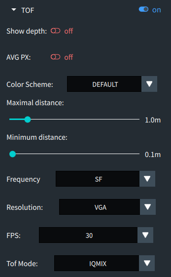
- Enable "TOF" to start TOF camera:

- The depth information of image can be controled by "Show depth" in menu:
The depth information of the current mouse position point will be displayed in the lower left corner of the display, which including the XY coordinate and the depth distance.
When "Show depth" is turned on, you can choose to turn on "AVG PX" to obtain the average depth information of points in a certain area. After turning on, a box will be displayed in the figure. You can move the box to obtain the average depth information of all points in the box, which is also displayed in the lower left corner of the image as below:

- You can switch the color theme of the TOF image through "Color Scheme" in the menu. Some effects are as shown in the figure:
Default:

Bone:

Ocean:

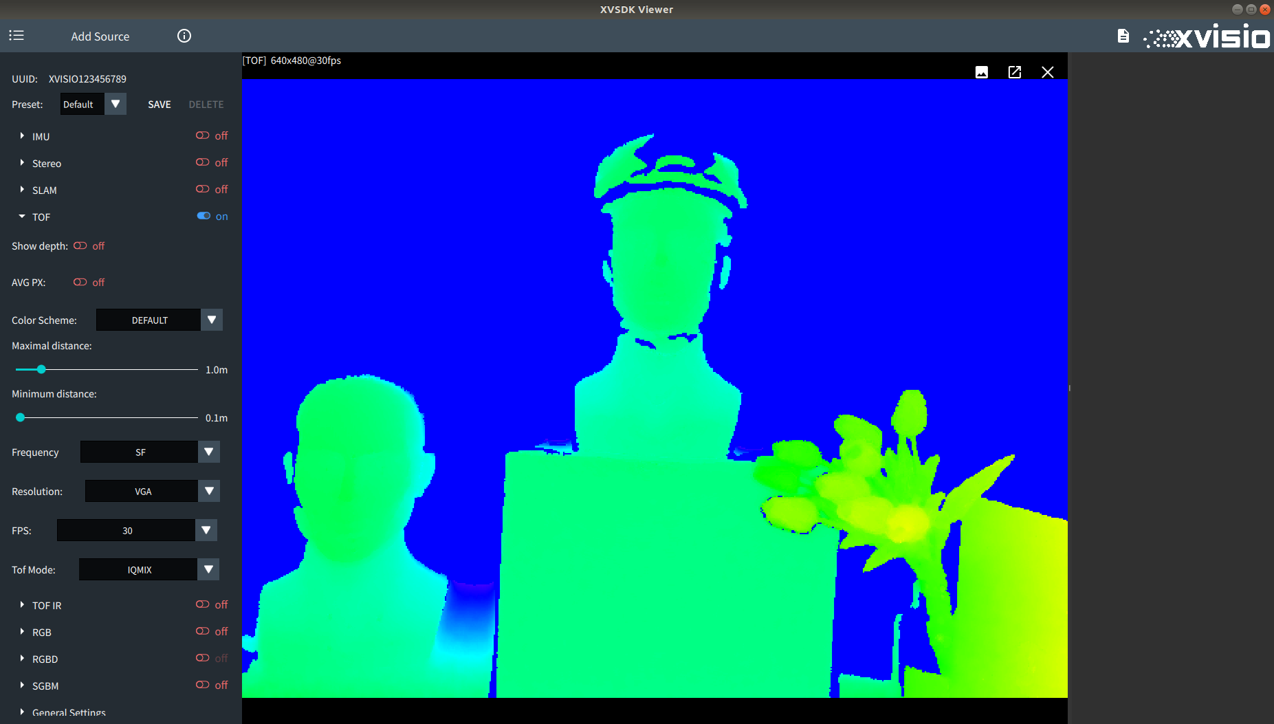
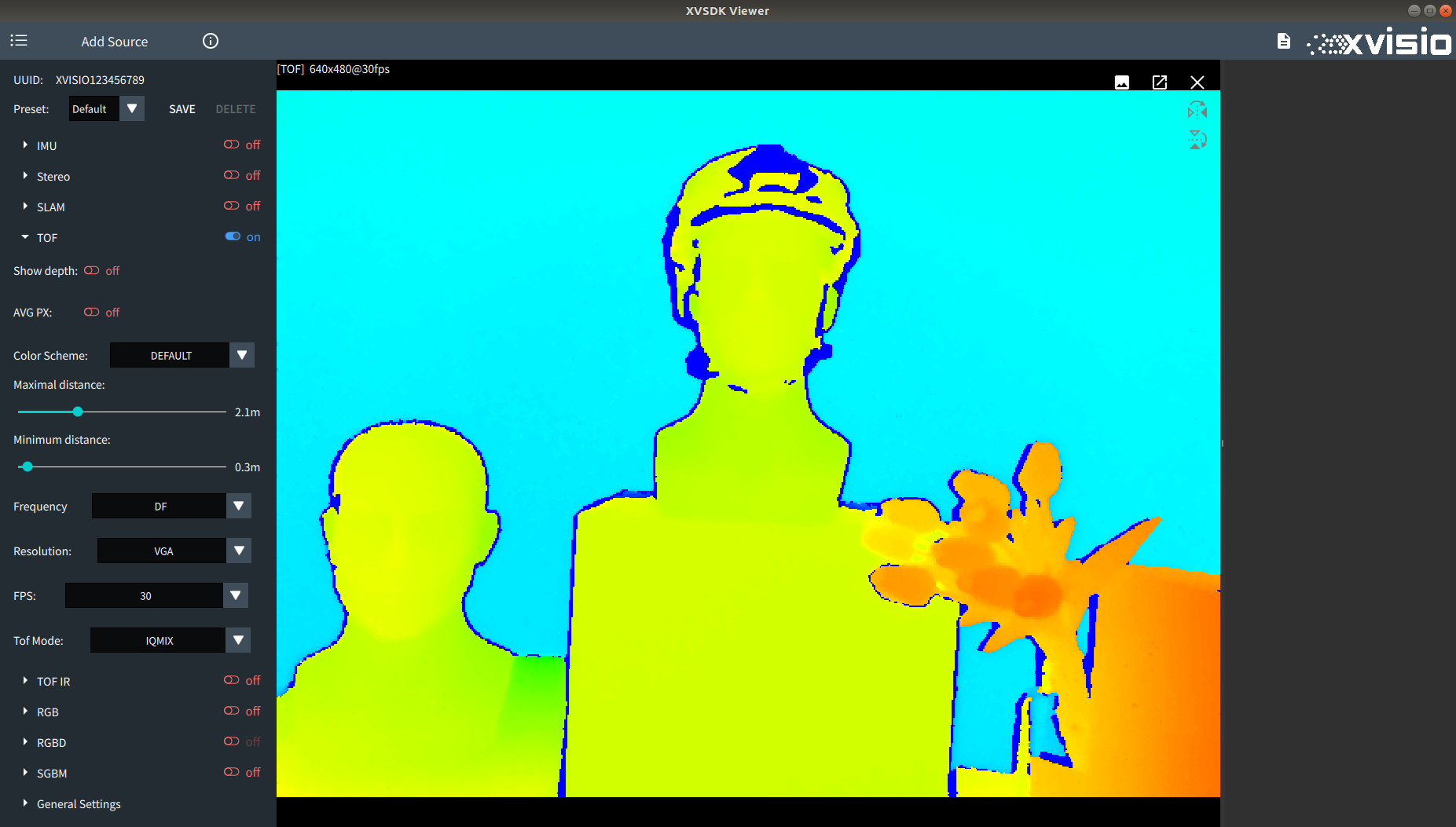
- The image drawing of TOF will adjust the color depth according to the distance. You can adjust the color of the image drawing by adjusting "Maximal/Minimum distance" in the menu to control the reference distance of the drawn image.
Default parameters:
Modify parameters( set "Maximal distance" to 2.1, set "Minimum distance" to 0.3):
- TOF camera will display different configuration items for PMD or SONY according to the manufacturer. If it is Sony camera, it will display as below:
Set “Frequency” and "TOF Mode" to control TOF frequency and work mode. Set "Resolution" to adjust the resolution of TOF camera. Refer to SONY TOF for detail information. - If it is PMD camera:
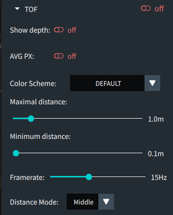
PMD camera provides three working modes. Once the mode is set, the corresponding frequency mode, frame rate and exposure time will be automatically adapted. Refer to PMD TOF for detail information.
2.2.5 TOF IR
- The TOF IR function can be turned on when TOF is turned on:

2.2.6 RGB
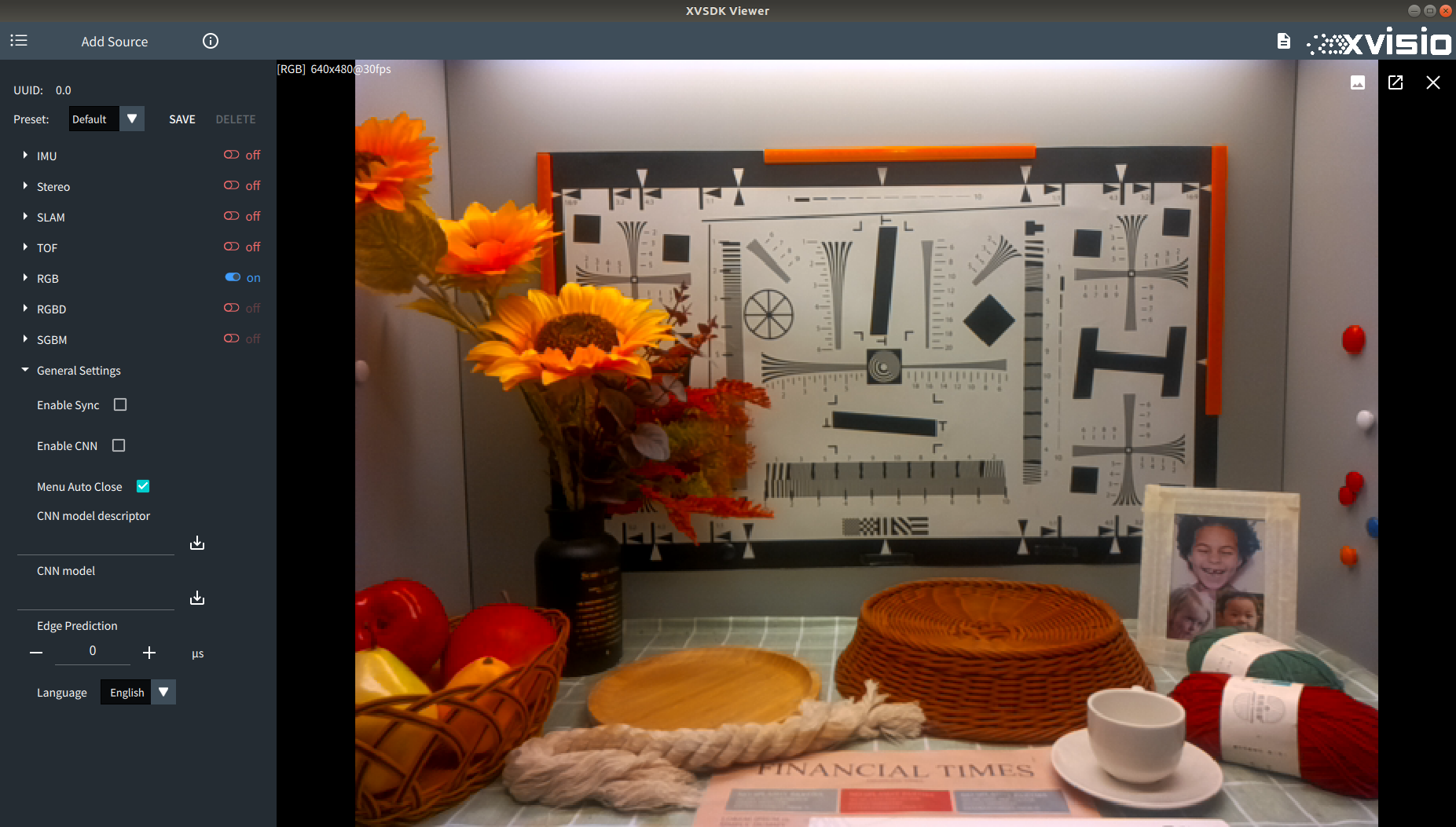
- Enable"RGB" to start RGB camera:

- User can adjust the resolution in the menu. Below three resolutions are supported:
- 1920*1080
- 1280*720
- 640*480

- The FPS can be freely setted within the range of 6-30:

2.2.7 RGBD
- The RGBD function can be turned on when both of the TOF and RGB are turned on:

2.2.8 SGBM
- Enable "SGBM" to start SGBM camera:

- Various configurations of SGBM can be adjusted in the setting menu. Refer to SGBM for detail functions. This section only demonstrates the effect of each function adjustment.
- "Dewarp" can be used to disable/enable the distortion correction function.
Enable Dewarp:

Disable Dewarp:

- Similar to the settings in the TOF camera, you can control whether to display the depth information of the image through "Show depth".

Similarly, the AVG PX function can be turned on to obtain the average depth information of points in a certain area. After turning on, a box will be displayed in the figure, and the average depth information of all points in the box can be obtained by moving the box, as shown in the figure:

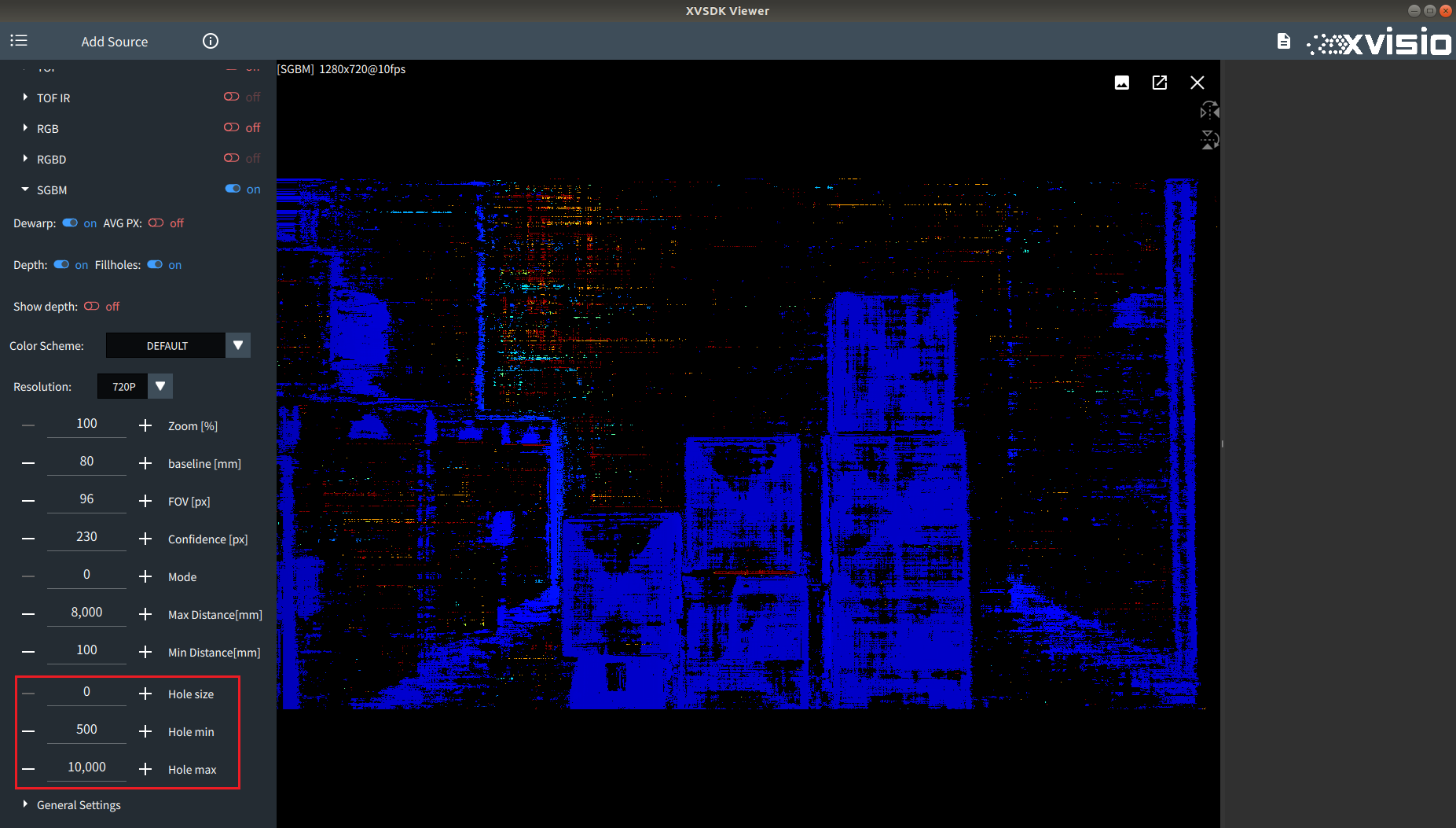
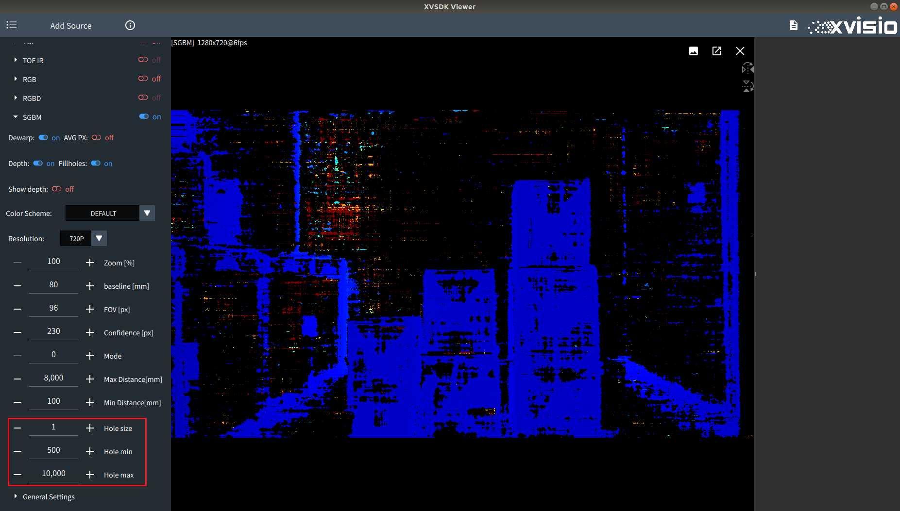
- Adjust the switch of "Fillholes" to control whether the filling invalid point function is enabled. After it is enabled, the corresponding configuration item will appear in the setting menu.

The fill efficiency can be controlled by adjusting the value of Hole size,Hole min and Hole max:
Before adjustment:
After adjustment:
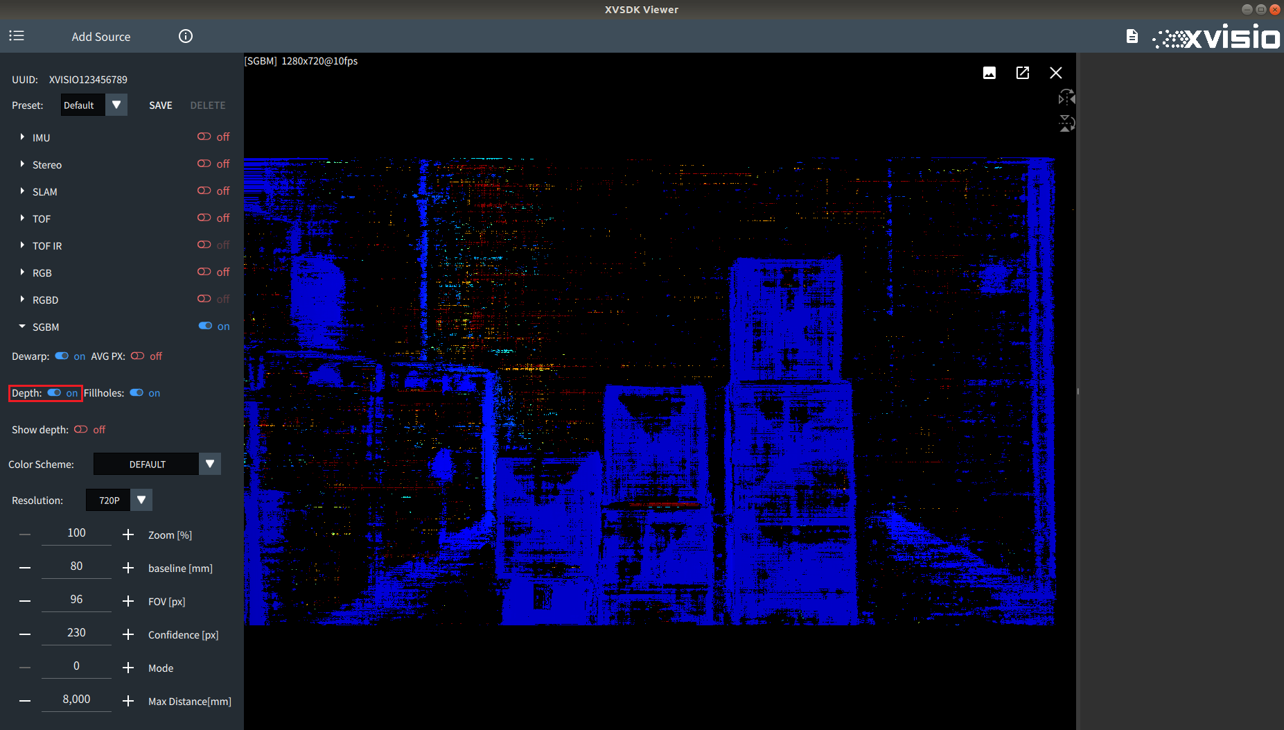
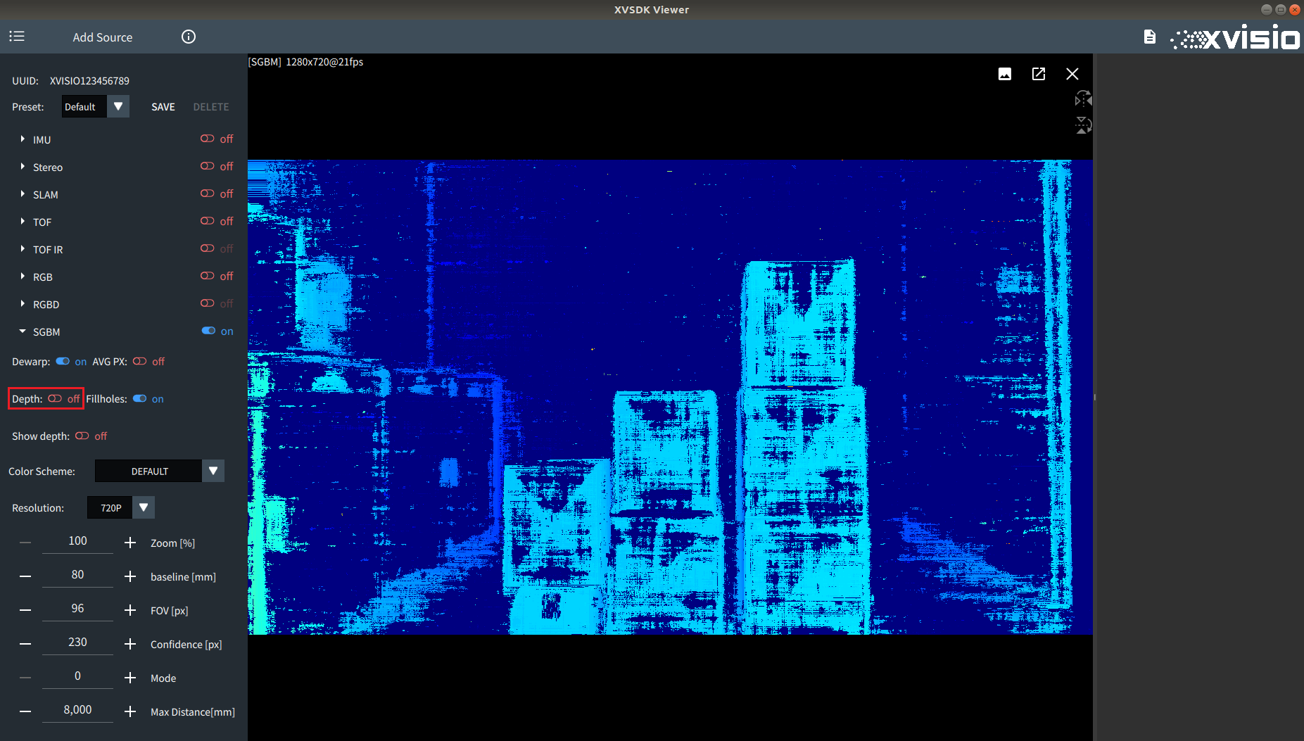
- Adjust "Depth"to control whether to draw according to the Depth data or Disparity data.
Enable Depth:
Disable Depth(enable Disparity):
- The color scheme of Sgbm image can be switched by "Color Scheme". See the images as below:
Default:

Bone:

Summer:

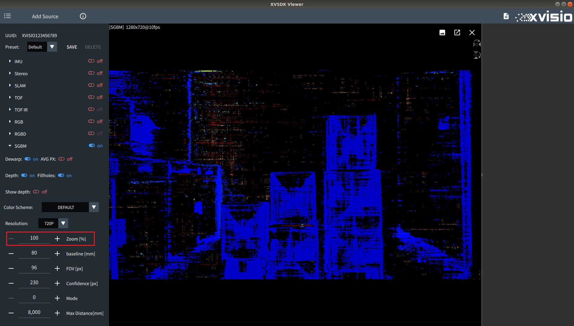
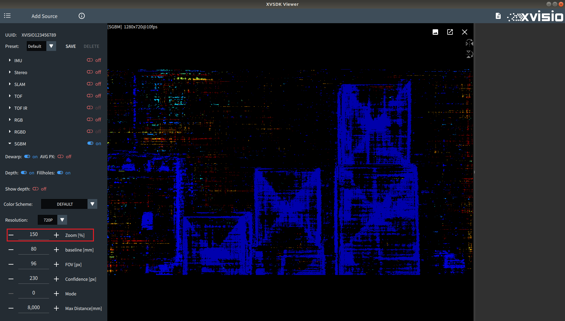
- The magnification of the Sgbm image can be controlled by adjusting the value of "Zoom". The default value is 100%. Refer to the comparison images as below:
100%:
150%:
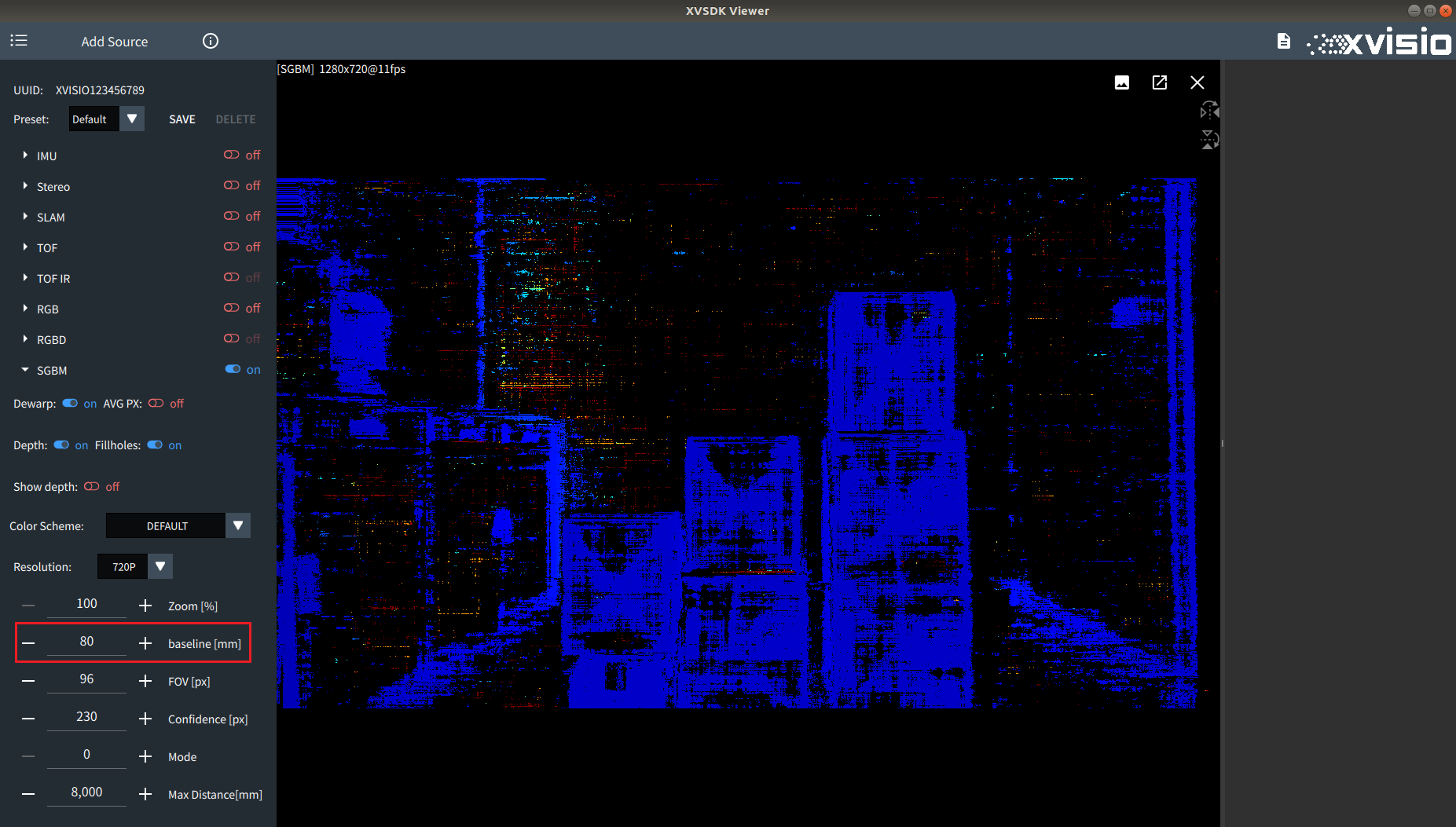
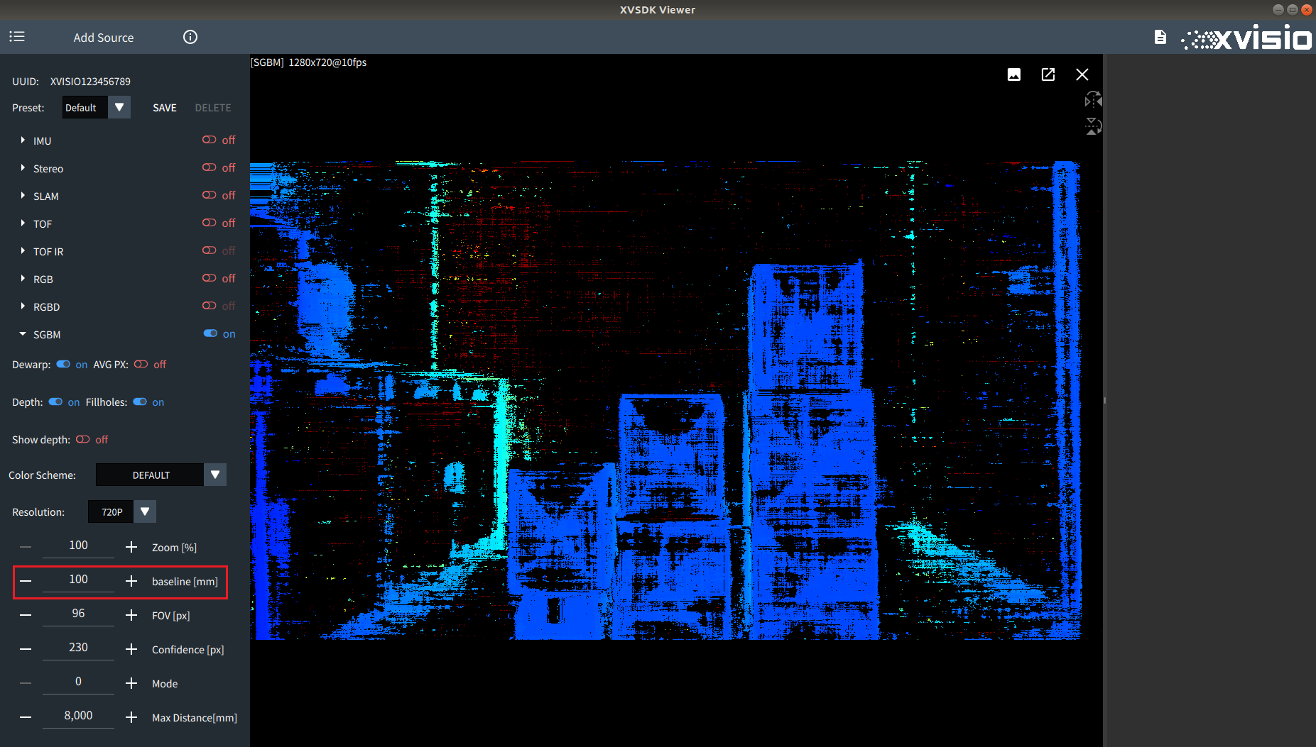
- The baseline of the camera can be adjusted by "baseline". The default value is 80mm. Refer to the comparison images as below:
80mm:
100mm:
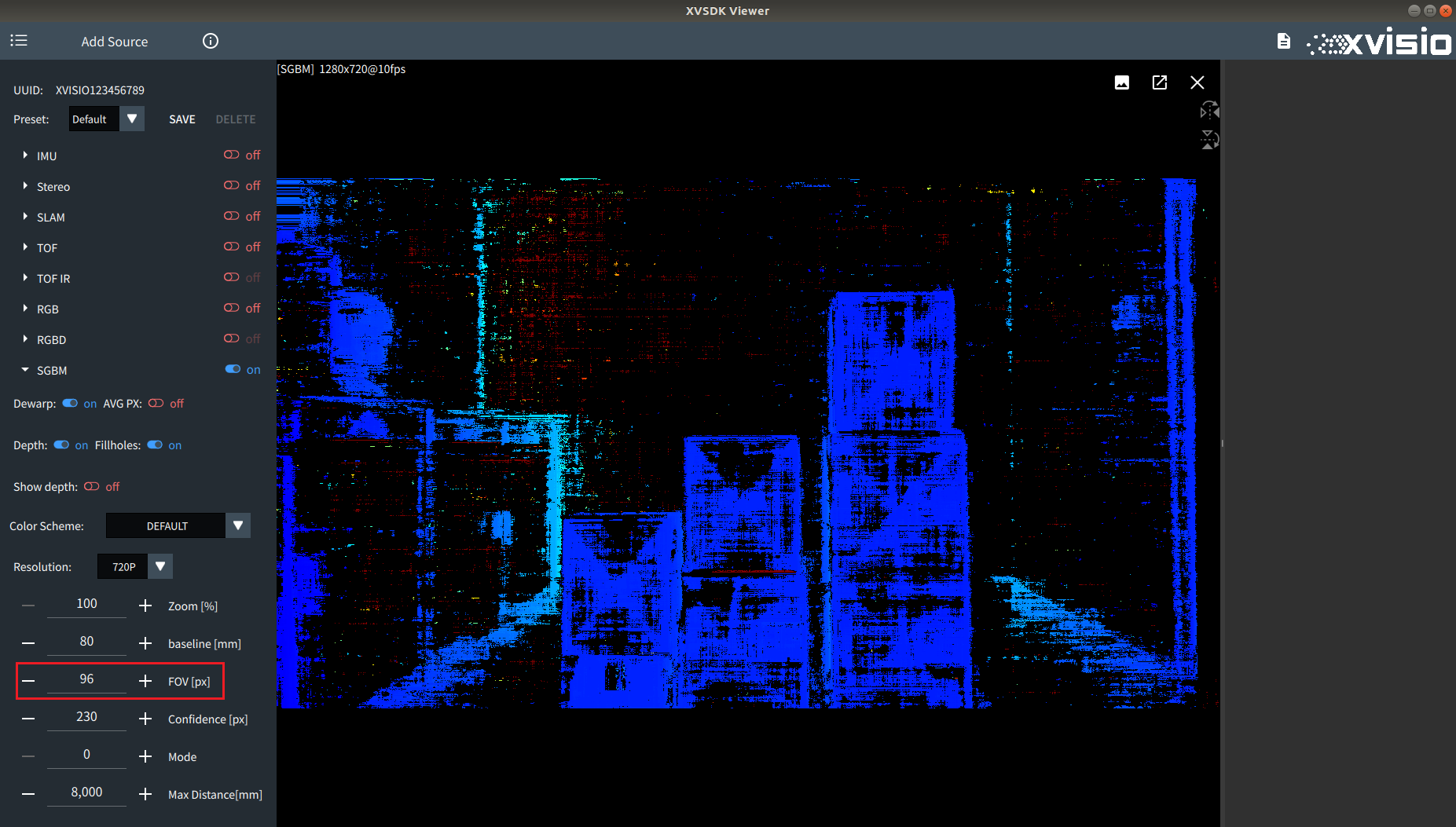
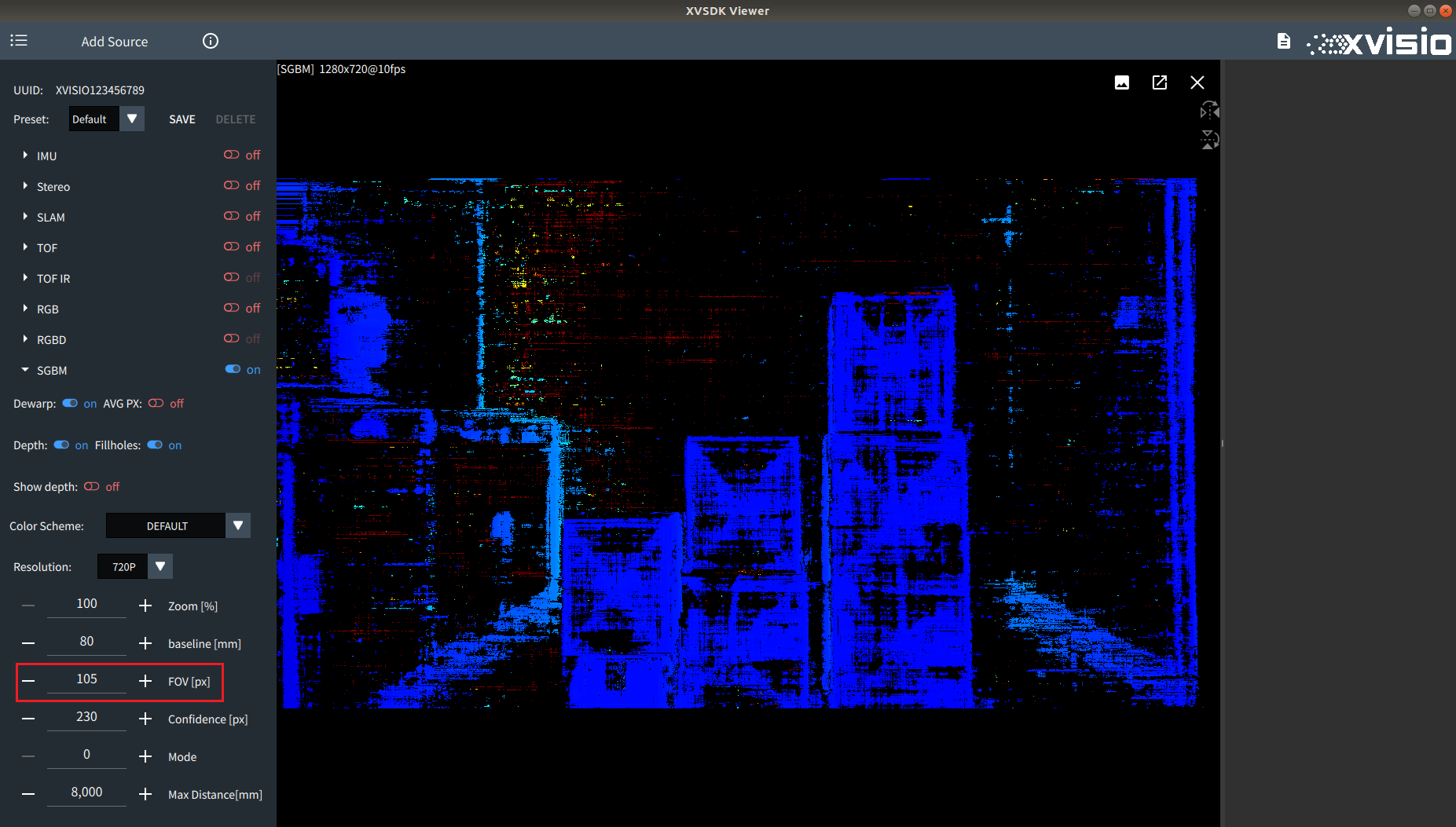
- By adjusting "FOV", you can adjust the effective FOV value of the binocular camera image applied to the SGBM algorithm. The default value is 96. Refer to the comparison images as below:
96px:
105px:
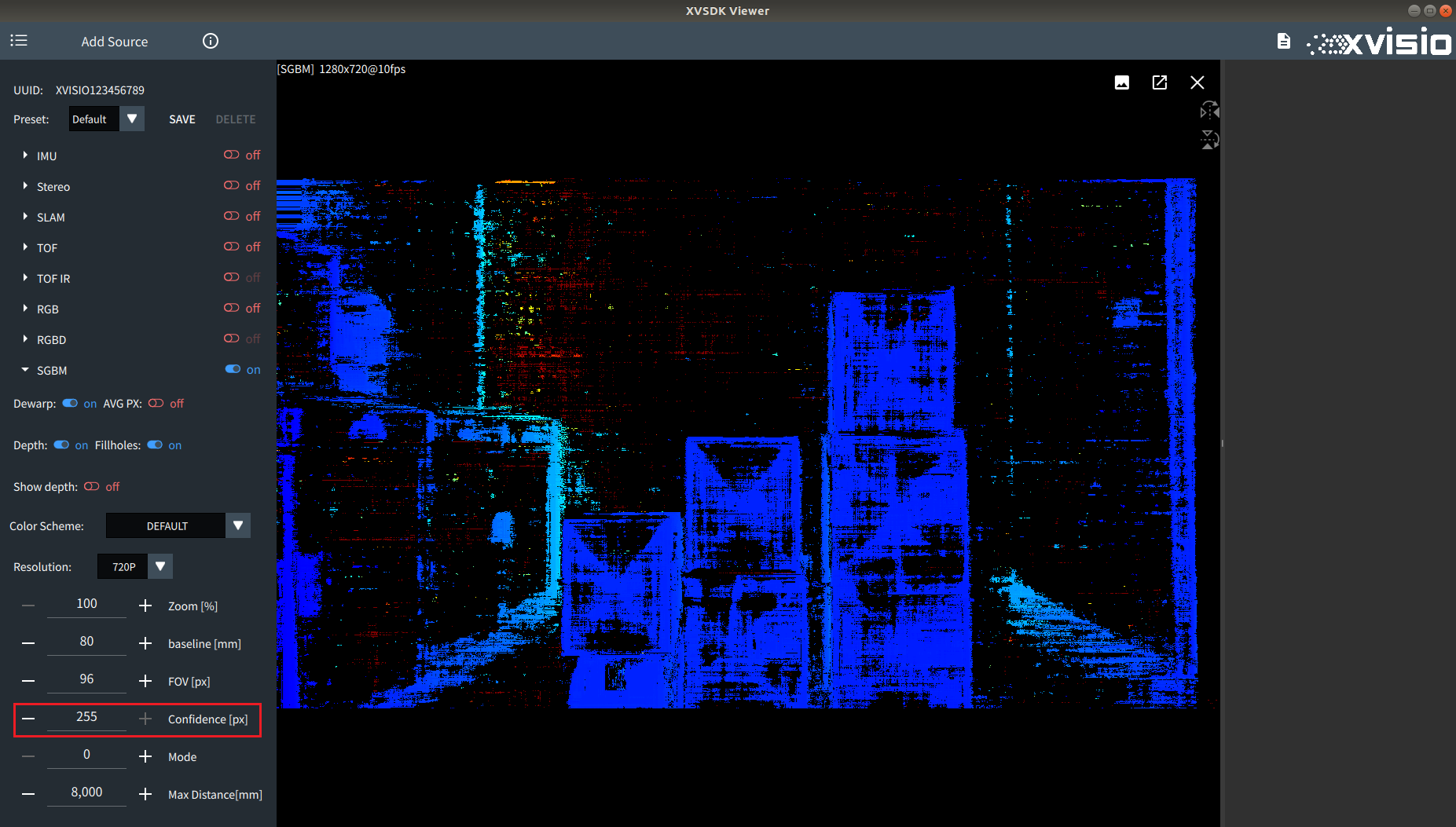
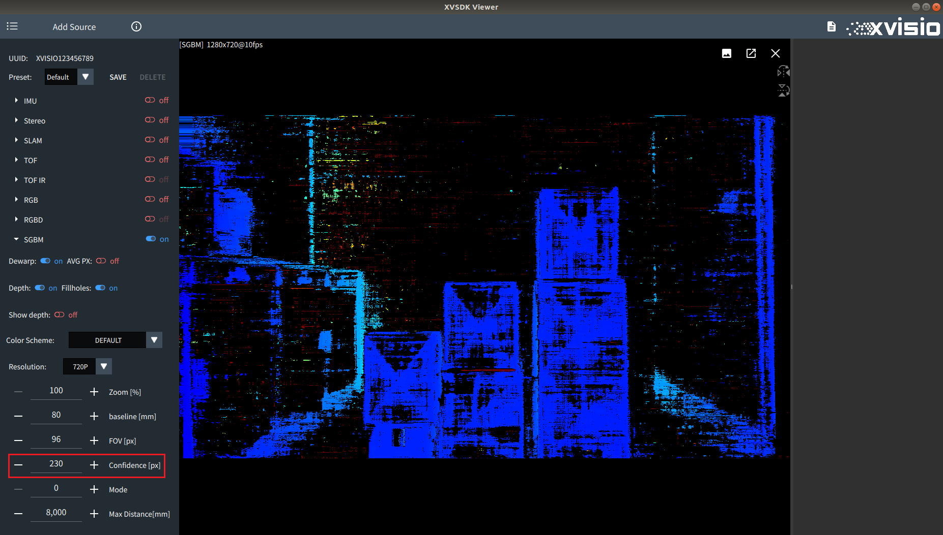
- "Confidence" is used to adjust parallax confidence value. Refer to the comparison images as below:
255px:
230px:
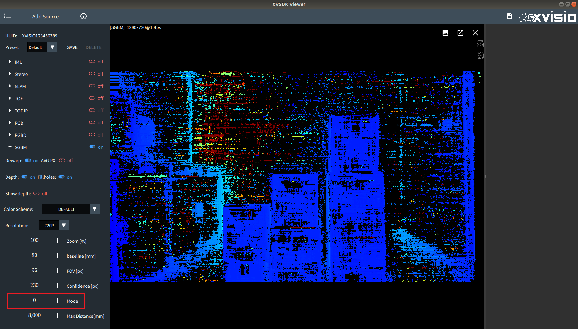
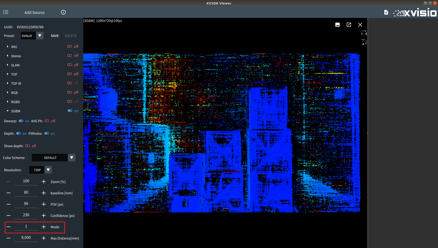
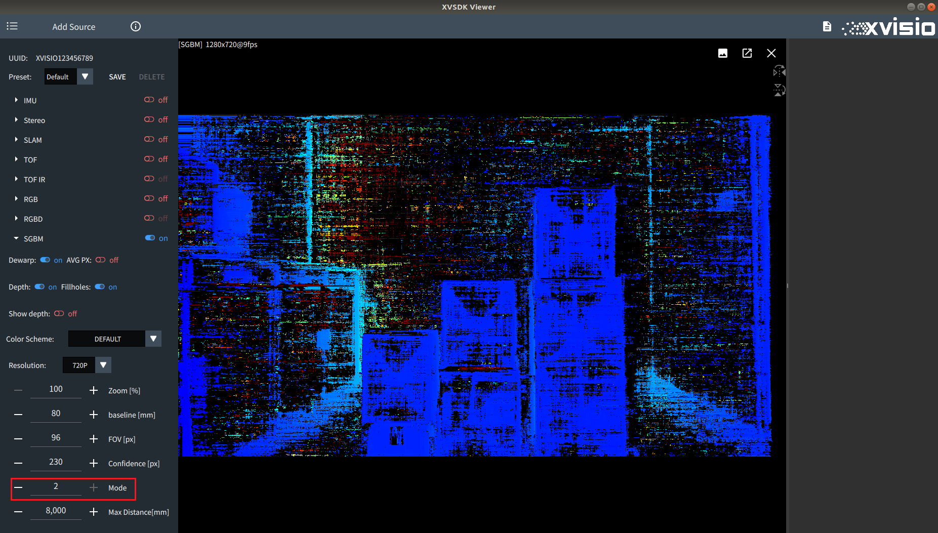
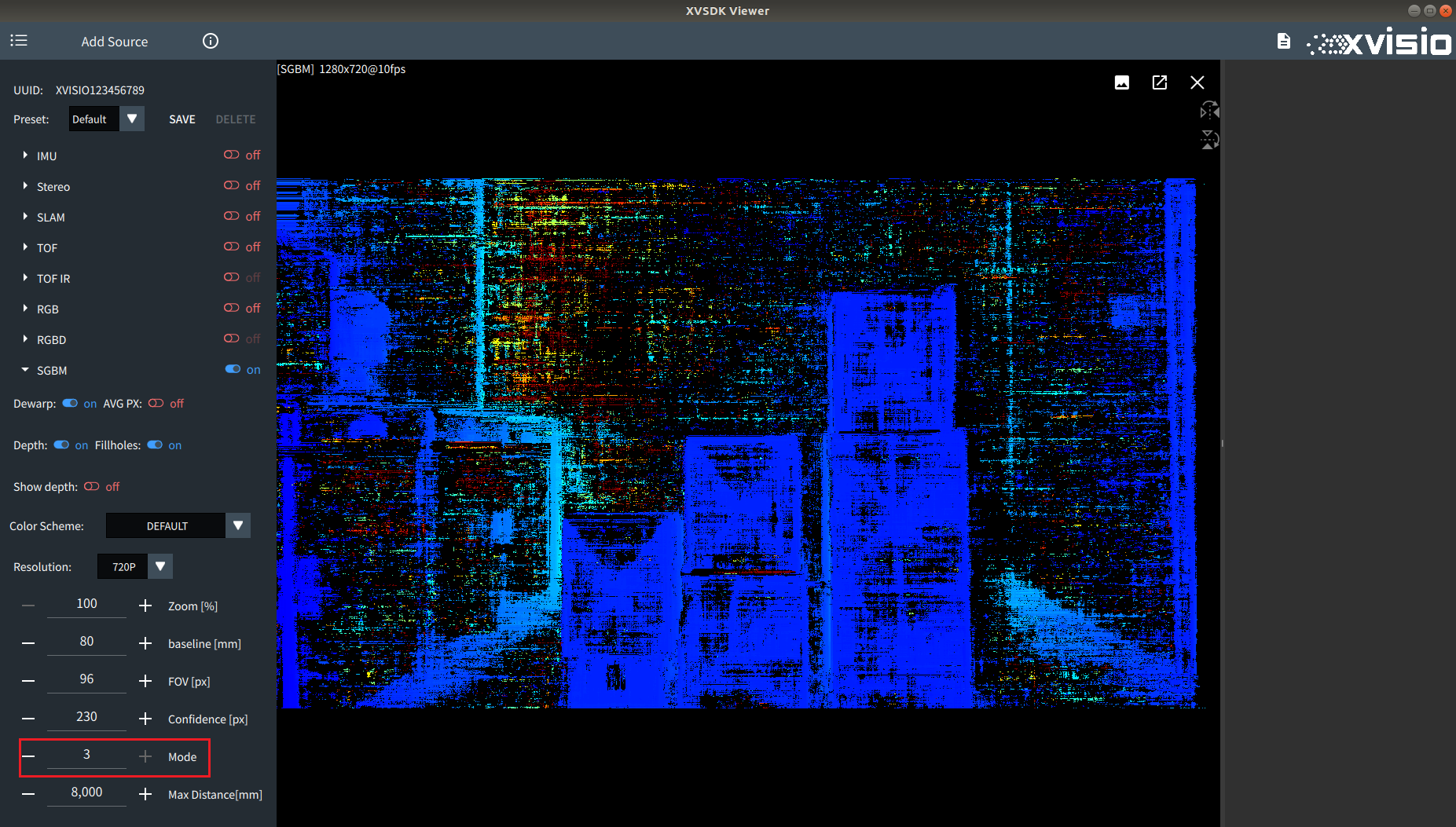
- "Mode" is used to switch Sgbm algorithm mode. The default mode is lrcheck mode. Refer to the comparison images as below:
lrcheck mode:
standard mode:
extended mode:
subpixel mode:
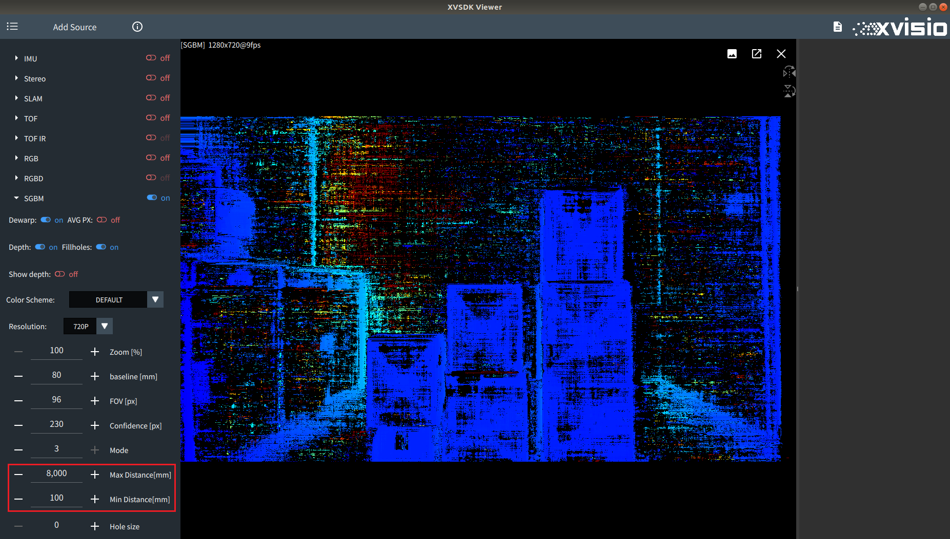
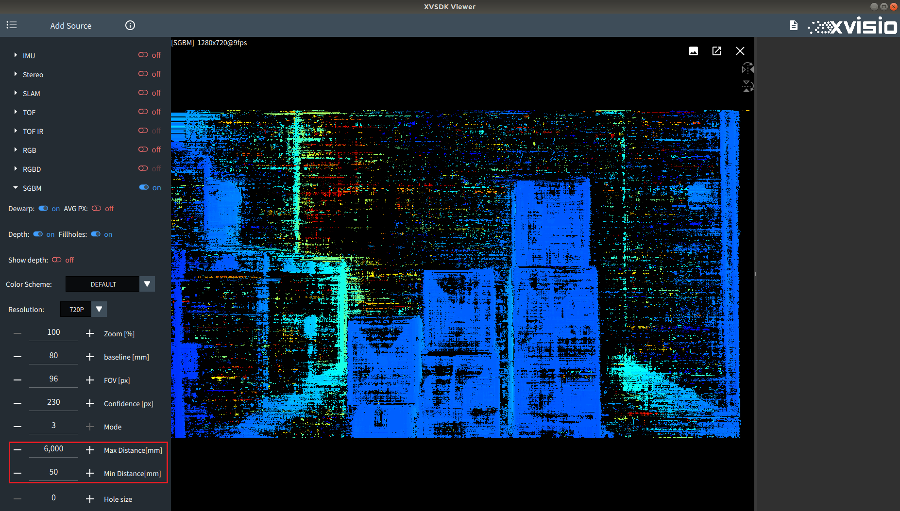
- "Max Distance" and "Min Distance" is used to adjust the value of max/min distance. Refer to the comparison images as below:
Default configuration (Max Distance is 8000,Min Distance is 100):
After adjustment (Max Distance is 6000,Min Distance is 50):
2.3 General Settings
2.3.1
- Check "Enable sync" to turn on the camera synchronization function.
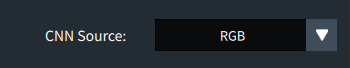
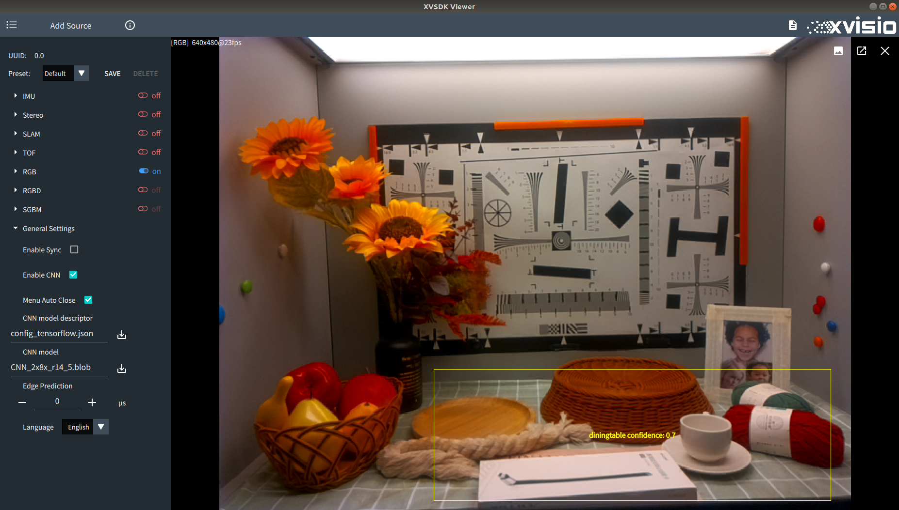
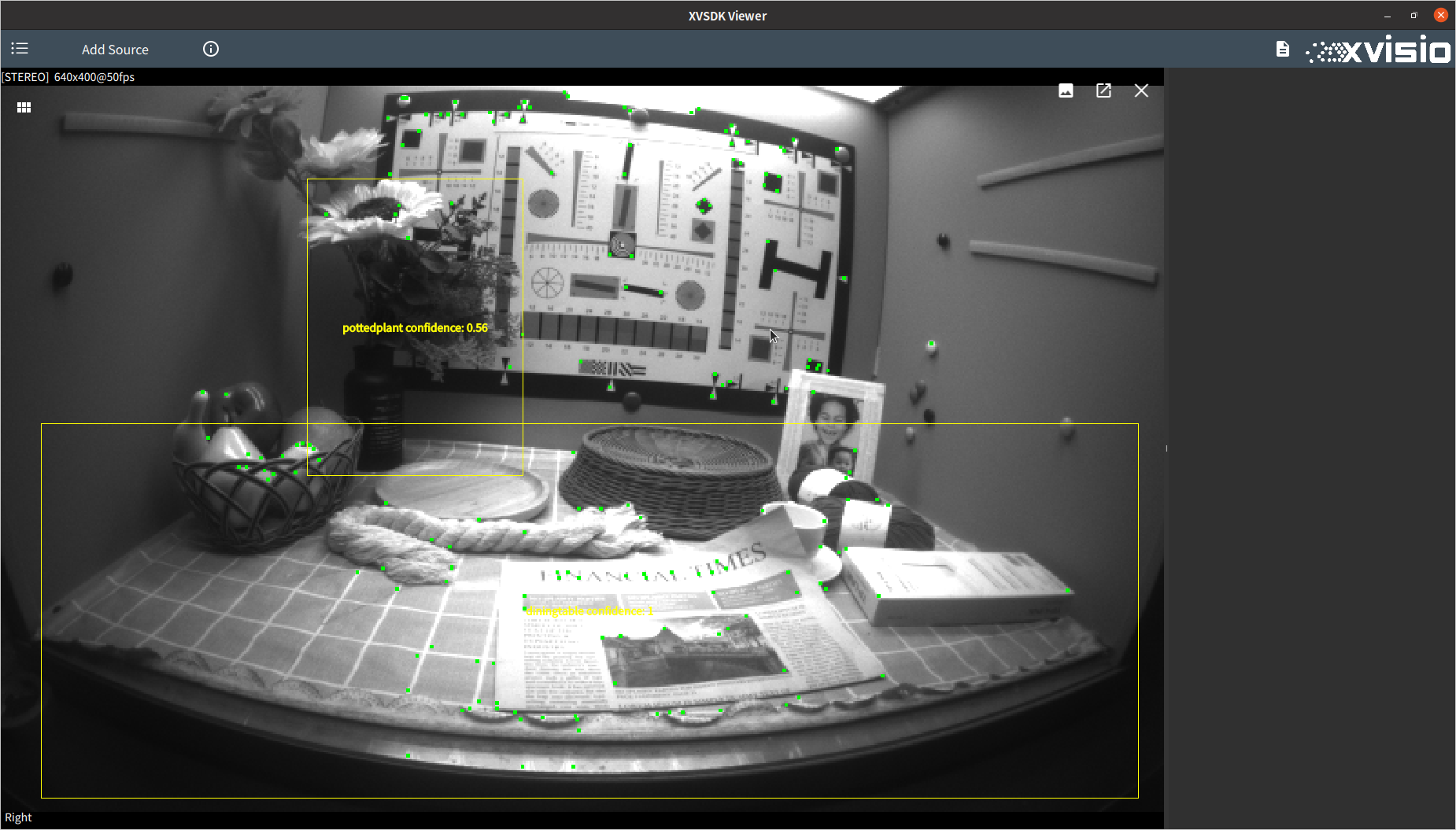
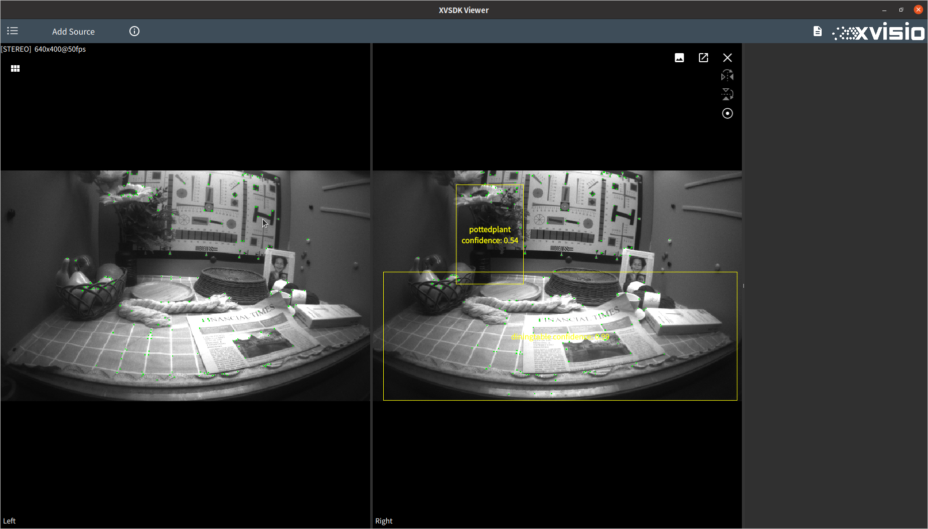
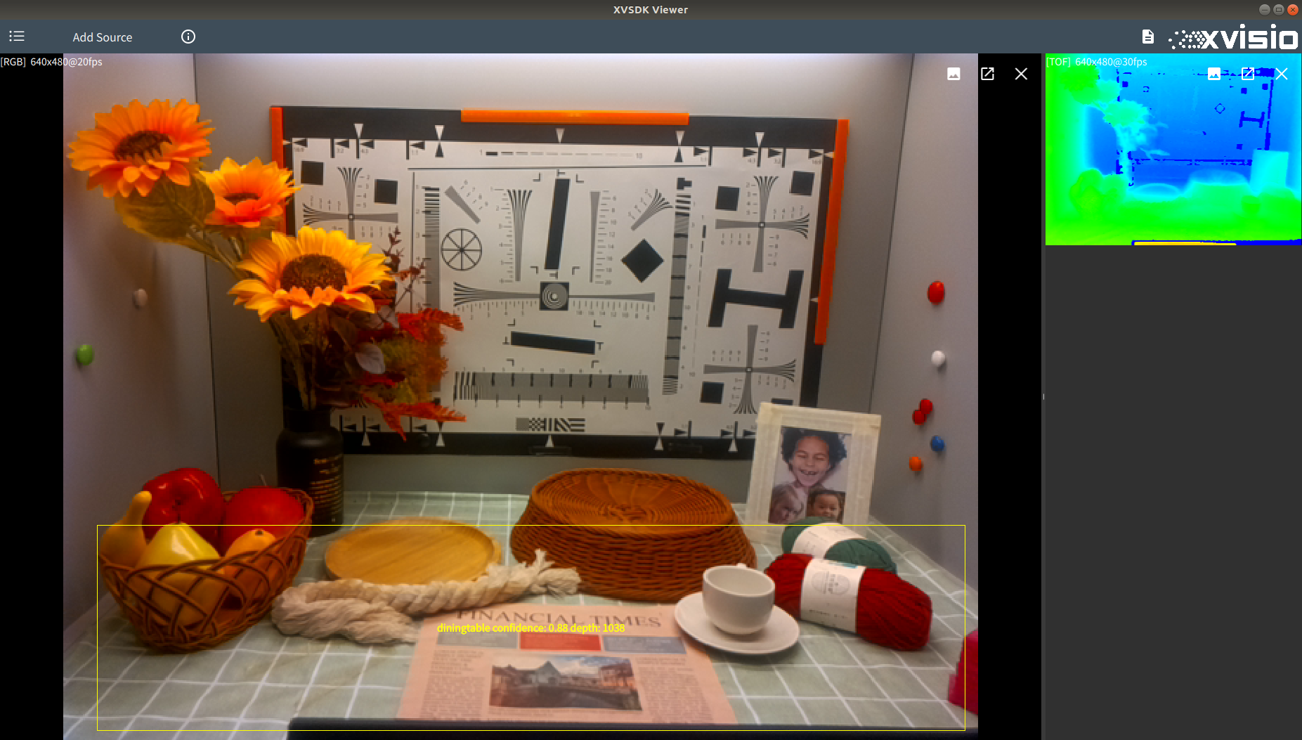
- Check "Enable CNN" to enable CNN function and then select CNN configuration file.Select json file in "CNN model descriptor" and select blob file in "CNN model", then turn on RGB or Stereo will start identify some objects and people, this can be adjusted by using CNN Source in the settings menu:
RGB:
Stereo Left:
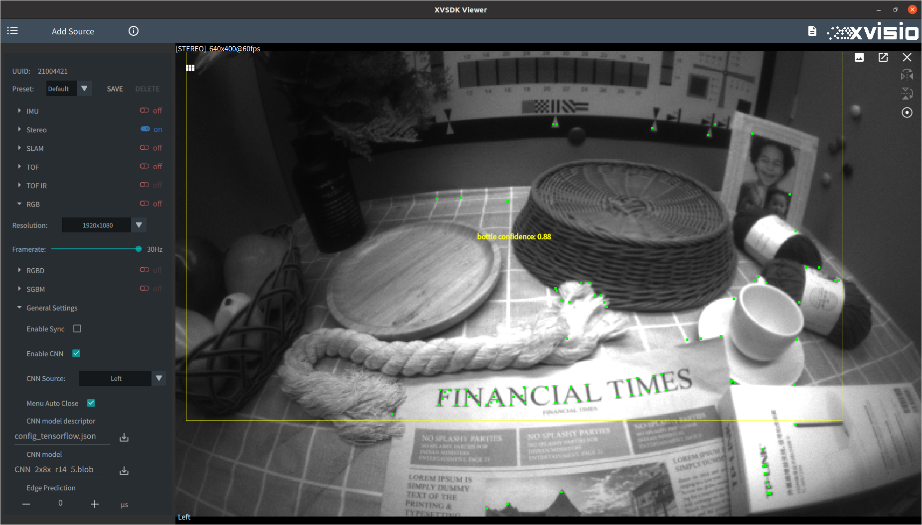
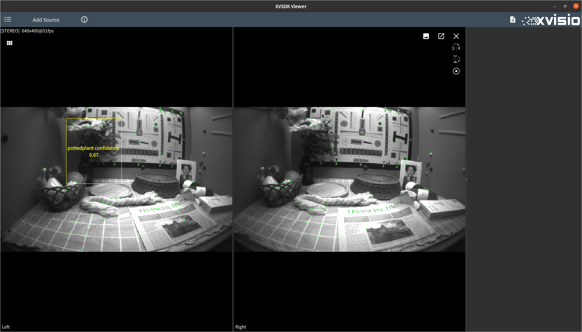
Stereo Right:
If TOF is turned on while the CNN function is started, the current depth information of the identified object relative to the camera will be displayed:
- "Menu Auto Close" is used to control the closing effect of the menu. If this function is checked, clicking on any external area will close the left menu bar. If it is unchecked, you need to click the menu button at the top left of the program to control.
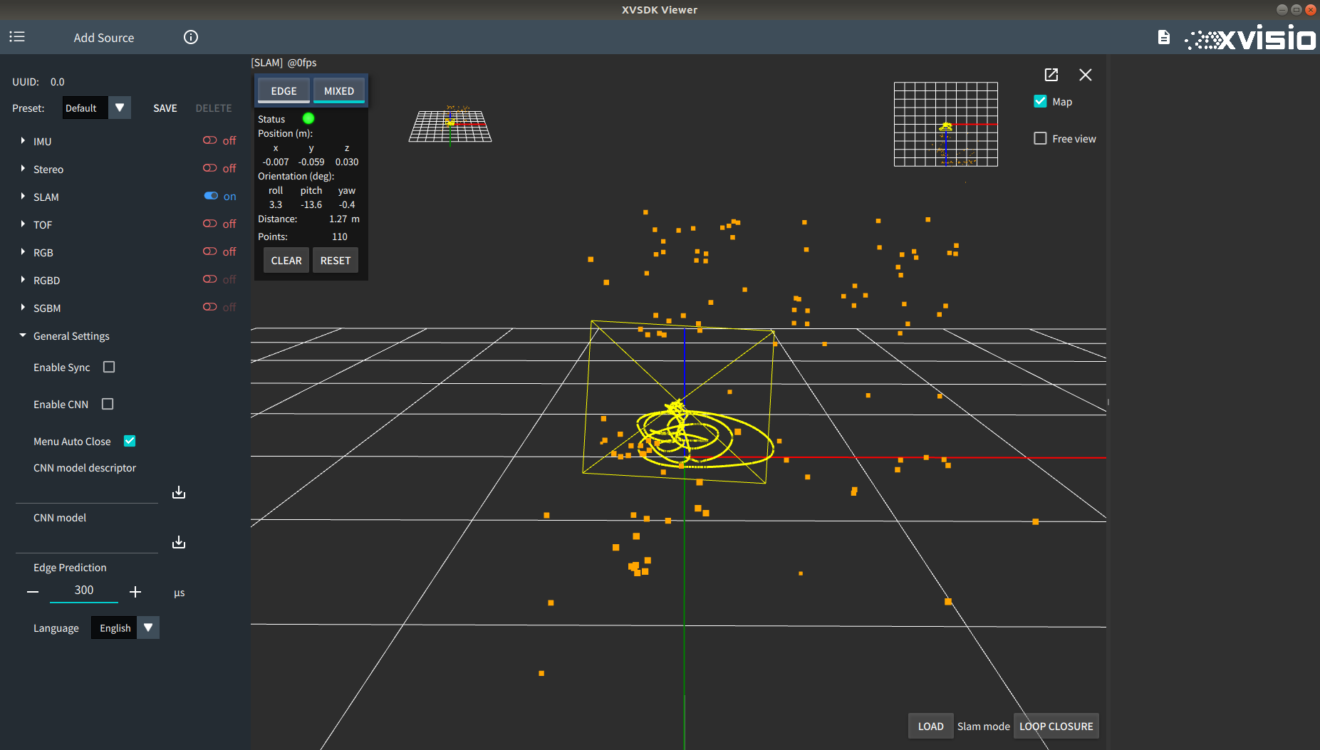
- "Edge Prediction" is used to adjust the prediction time for the edge trajectory. Refer to the comparison images as below:
Default setting (0μs):
Modify to 300μs:
- "language" is used to switch system language:
2.4 Other Settings
- The default configuration effect is saved in Xvsdk Viewer. You can switch all options to default values by selecting "Default" at the top of the menu.
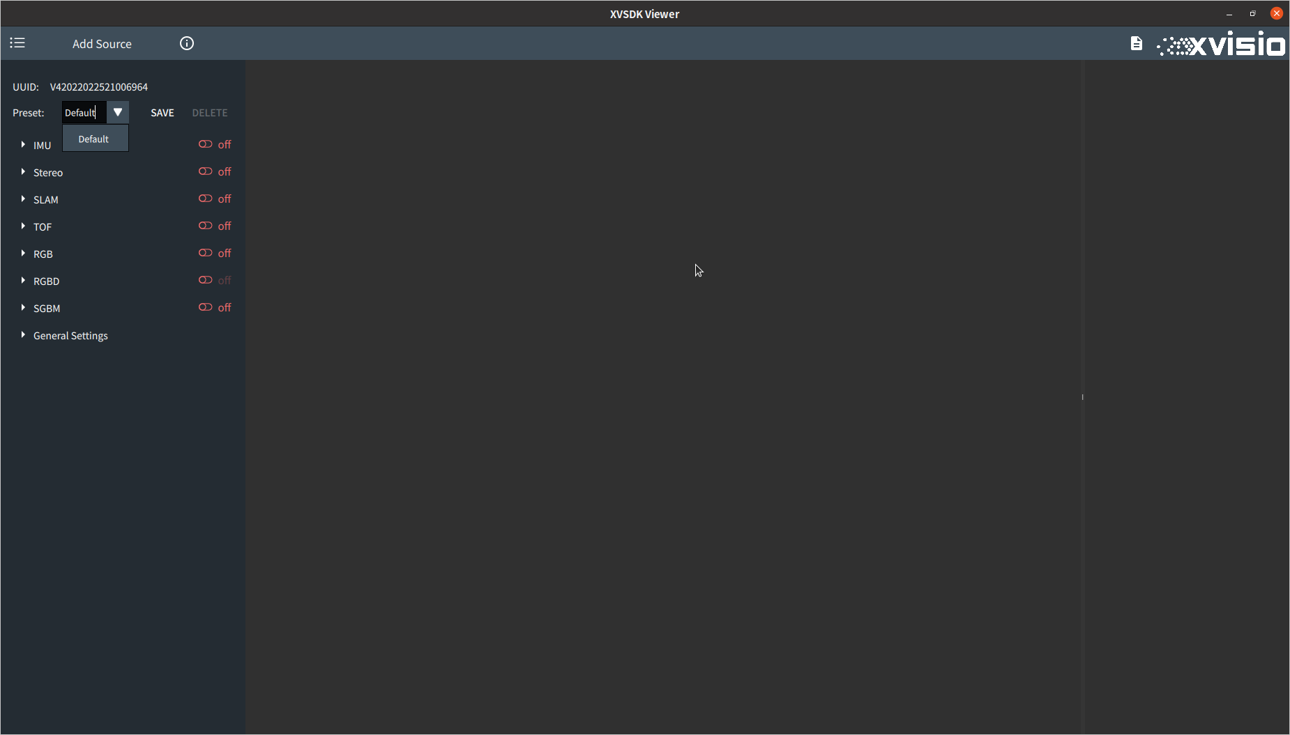
- If you need to save your preference settings, you can rename it in "Default" drop-down menu after setting, and then click "SAVE" on the right to save the current settings.

The saved setting also can be deleted by "DELETE". Note that the default setting can't be deleted. - When multiple cameras are turned on, you can switch the specific display effect through the button at the upper right corner of each view. If the current display effect is a home view, the other cameras will be placed vertically on the right side of the home view.
You can switch to the main view by clicking the maximize button of any camera on the right:


If you click the maximize button of the main view, it will switch to the tile display mode:
- Click the maximize button of any view in the tiling mode to switch to the main view mode and set the selected view as the main view:


- In addition to turn on / off a camera in the left menu bar, you can also turn off the current camera through the close button at the upper right corner of each view:
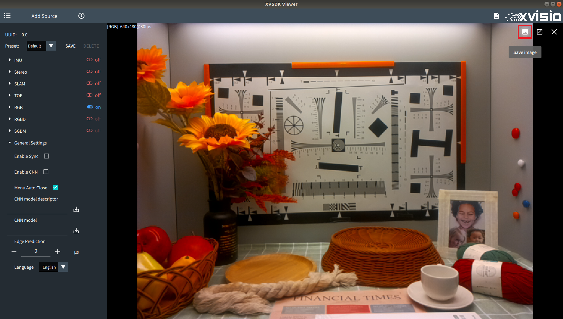
- If the opened camera is one of Stereo, TOF, RGB and SGBM, you can save the current camera image through the "Save Image" button in the upper right corner (both of the camera will save the images in PNG. TOF will save the files in PCD additionally).
← Xvisio SDK Documentation Home Page